Excavation of the UK’s first “caterpillar shaft” is underway for a key structure on High Speed 2 in London.
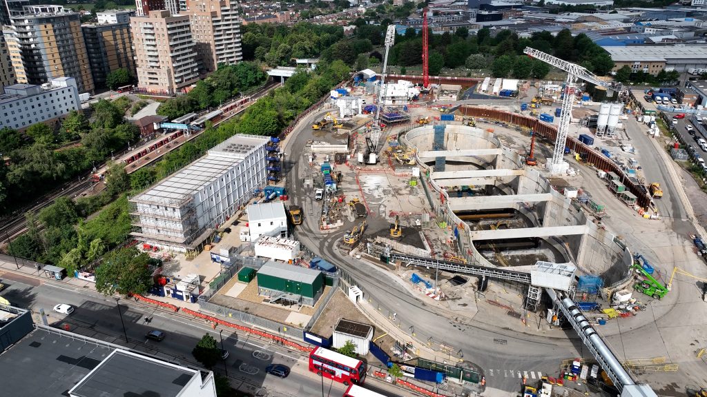
West London’s Old Oak Common station will become one of the country’s most vital transport hubs when it opens. It will have 14 platforms – six for High Speed 2 (HS2) trains and eight for other rail services.
Construction is progressing so it can be ready when HS2 Phase 1 is completed sometime between 2029 and 2032.
Right now, excavation of a key below ground structure for trains approaching and leaving the station is also advancing. Known as the Victoria Road Crossover Box (VRCB), it is a few hundred metres west of the station and is thought to be a UK design first.
It will enable HS2 trains to switch tracks as they approach or leave Old Oak Common station. Two tracks, one for each direction, will run diagonally across VRCB and cross each other.
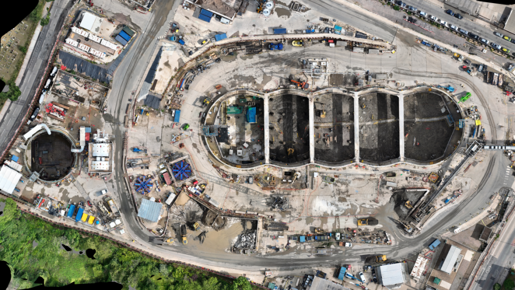
Viewed from above, VRCB’s design resembles the shape of a caterpillar with five so-called “bubbles”, making it the first caterpillar shaft to be excavated in the UK.
Design House – comprising Arup, Typsa and Strabag – is VRCB’s design engineer and Skanska Costain Strabag Joint Venture (SCS JV) is the main contractor, delivering the work as part of its £3.8bn contract on HS2 which includes the construction of the project’s tunnels in London. Subcontractor Züblin is constructing the diaphragm wall.
VRCB will provide additional flexibility as it will enable trains to switch tracks if one of the bores for the 13.5km long Northolt tunnel to the west of the box or the twin 360m sprayed concrete lining (SCL) tunnels eastwards to Old Oak Common station are closed for maintenance.
The structure helps cool and ventilate the tunnels, as the box will remain open to the sky enabling air to circulate and ambient temperatures to cool them down. It will also be used for the launch of one of the two tunnel boring machines (TBMs) used to drive the eastern 5.5km section of the Northolt Tunnel.
Arup major projects director Kate Hall says caterpillar shaft excavation has been used before in Hong Kong, Singapore and Brazil. In Hong Kong a 500m long caterpillar-shaped shaft with 15 “bubbles” was excavated for the construction of Tuen Mun to Chek Lap Kok subsea road link. In Brazil, one with five bubbles was excavated at Brooklin Station in São Paulo, during the construction of Metro Line 5.
Hall says VRCB is “very similar in dimensions and geometrical definition” to the one in São Paulo.
She specifies that caterpillar shafts have been predominantly used as temporary TBM launch shaft structures, in contrast to VRCB which will be a permanent structure “requiring a different level of reliability and design”.
Design change
HS2’s reference design involved the construction of a 250m by 33m rectangular box with a 47.5m deep, 1.8m thick continuous reinforced concrete diaphragm wall. It featured three levels of struts – 16 at each level – and 250, 1.8m diameter tension piles extending to 40m depth.
At the initial stage of the design, an optioneering process was carried out to identify potential improvements to the reference design.
“There were more than 30 different concepts for the design of VRCB, although we quickly focused on several variations of the caterpillar design as we found significant advantages over the more traditional rectangular box,” says Hall.
“The beauty of this caterpillar structure is its resistance to lateral pressure mainly by means of horizontal hoop forces developed by the arching shape of the diaphragm wall panels.
“This avoids a closely spaced strutting system needed by a conventional rectangular shaped straight diaphragm wall arrangement.”
The beauty of this caterpillar structure is its resistance to lateral pressure mainly by means of horizontal hoop forces
The hoop forces are transferred to the buttress elements where each bubble connects with its neighbour. The buttresses run vertically and are supported by top and intermediate props as well as cross walls under the base slab.
Hall says this design generates compression forces on the reinforced concrete, the most efficient way to work with this material.
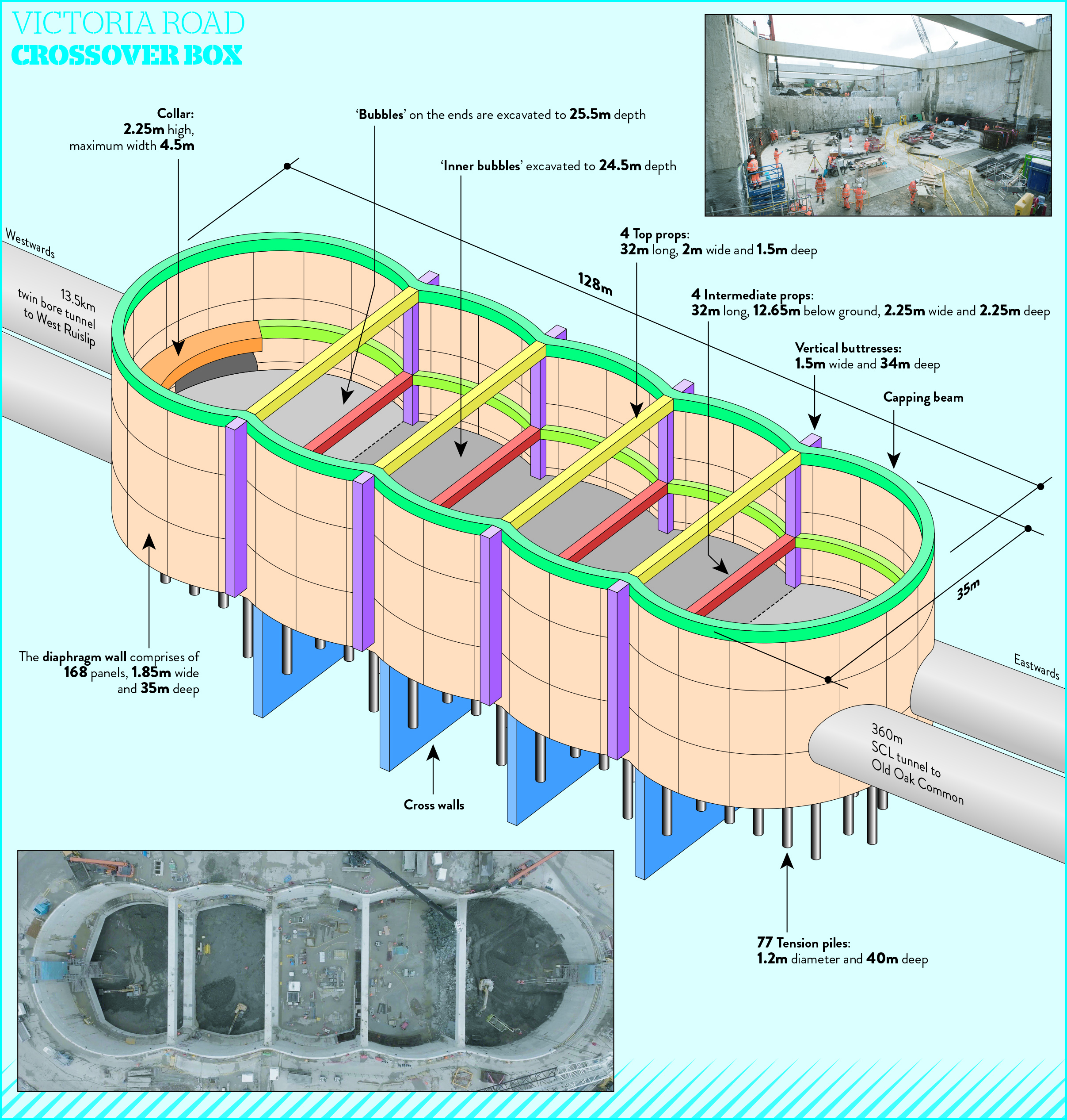
After several rounds of optimisation, the final design features a considerably smaller crossover box than the reference design. VRCB is 128m long, 35m wide, 25.5m deep and comprises five bubbles.
The diaphragm wall around the perimeter comprises 168, 1.85m wide and 35m deep panels.
The vertical buttresses are 1.5m wide and reach a depth of around 34m. They are Y-shaped with two wing reinforcement cages on the sides and a main buttress reinforcement cage in the middle.
The four rectangular concrete props at the top which connect the tops of each buttress are 2m wide by 1.5m deep, while the four intermediate props – 12.65m below ground – are 2.25m wide by 2.25m deep. All props are approximately 32m long.
The risk of site congestion due to props was eliminated
The end bubbles are approximately 9m longer than the inner ones and will have a 2m thick base slab, double the thickness of the base slab for the inner bubbles. SCS JV sub agent Jan Schumacher says the reason for the thicker base slabs of the outer bubbles is that they will be more stressed with higher dynamic loads because they have to accommodate the tunnel openings.
The ovoid shaped tunnel openings’ breakout profile is approximately 12.2m wide and 10.7m high.
The first TBM for the Northolt Tunnel will be launched from inside the westernmost bubble.
A 50m SCL tunnel will connect the westernmost bubble with the Victoria Road Ancillary Shaft where the second TBM will be launched after it has been assembled in VRCB.
This shaft has an internal diameter of 25m and will provide ventilation and emergency access to the tunnels when HS2 is in operation.
The front part of the second TBM will be lifted directly into the ancillary shaft, while the other parts will be lifted into the crossover box and pushed through the SCL tunnel.
The easternmost bubble will be linked to Old Oak Common station by two 360m long SCL tunnels with a maximum height of 12m and width of 14m.
Above the tunnel openings in the caterpillar structure concrete collars have been constructed at a height of 2.25m. Their width varies with the maximum being 4.5m. They will help with the distribution of hoop stresses around the tunnel openings.
Comparative advantage
The way horizontal hoop forces are distributed in this structure has enabled a 49% reduction in VRCB’s length compared to the original design. The number of tension piles was reduced by 69% to 77, due to the smaller footprint of the box and the introduction of an under slab drainage system which reduces uplift forces and ground heave pressures.
The lower number of piles and smaller footprint resulting from the design change contributed significantly to a reduction in the volume of concrete needed for VRCB from 100,000m3 to 57,000m3.
Schumacher adds that because fewer materials were needed, the carbon footprint of this part of the project was lowered with a 42% reduction in embodied carbon to 40,490t CO2e.
In terms of construction, the excavation volume of the caterpillar shaft was 183,000m3, much less than the 300,000m3 that would have been needed for the rectangular crossover box in the reference design.
Another benefit of having a smaller structure is that it frees up more land for future development.
Hall says site safety was also enhanced. “The risk of site congestion due to props was eliminated and excavation equipment was able to work in an unrestricted manner. The elimination of propping levels will also allow fast tracking of all related activities,” she adds.
Construction
SCS started permanent works on site in January 2021. Schumacher says the team started by installing the 77 tension piles, which are 1.2m in diameter and 40m deep. It began diaphragm wall construction in August 2021.
The biggest technical challenge for the project team has been the geometry of the diaphragm wall.
“It’s mainly the diaphragm wall construction that is challenging. All the angles are not 90° as they normally would be,” says Schumacher.
Work on the diaphragm wall started with the installation of a working platform and guide walls followed by the construction of the diaphragm wall panels.
The diaphragm walls were excavated in a series of “bites” using a hydraulic grab. Three bites were needed for each panel with the ground supported by bentonite slurry.
Steel cages were then inserted and the bentonite slurry was replaced with concrete.
The reinforcement cages for the eight buttresses were fabricated on a site across the road from VRCB. Approximately 87t of steel and 500m3 of concrete were used for each buttress.
The construction of the diaphragm walls was completed a year ago and capping beam construction followed.
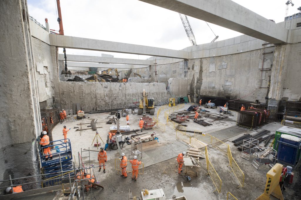
Excavation works started shortly after and have progressed well, as they are in London Clay which makes for relatively easy digging. Installation of the intermediate props finished in May.
The end bubbles will be excavated to 25.5m below ground and the inner ones to 24.5m. The excavation of the westernmost bubble was prioritised as it will be handed over to the tunnelling teams this autumn. Now that this bubble has been fully excavated, construction of its base slab has started.
The bubble adjacent to this one also reached base slab formation level when NCE visited the site.
Moving eastwards, the other bubbles were excavated to 23m, 22m and 18m below ground respectively by late July.
Work on site is expected to finish in 2026. Schumacher says the benefits of the caterpillar design “outweigh any construction difficulties” and he believes that similar structures could be built elsewhere in the UK in future.
Like what you've read? To receive New Civil Engineer's daily and weekly newsletters click here.
Have your say
or a new account to join the discussion.